WOODWARD GOVERNOR
OBJECTIVE
The objective of this unit is to make you understand about
· the principle of governing
· duties of governor in locomotive engine and their types
· features of woodward governor
· hydraulic circuits pertaining to different activities of governor
· testing of governor
· trouble shooting of governor
There is a particular RPM at which the efficiency of the engine is highest. This Rpm is guided by the pre assigned load to the engine. But the RPM of engine gets varied if the load on the engine gets changed. Hence to maintain the RPM constant, Governor is applied in the engine. The Governor basically makes the correction of engine speed by changing the amount of fuel supply into the engine, they are called speed governors. In the locomotive engine where fixed throttle system exists, Governor is required to maintain both the RPM and HP constant at any specific notch (throttle position). As such in the locomotive besides fuel correction, correction is made on the load also.
Depending upon how the Governor recognises the engine RPM and actuates for its correction the governors are classified as mechanical, hydraulic or electric. Sometimes they work in combination like mech-hydraulic, electro-hydraulic etc.
In all the diesel electric locomotive of Indian Railways either GE (electro hydraulic) or Woodward (hydraulic) governors are used.
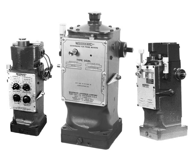
The Woodward governor for locomotive applications is a
standard hydraulic governor which regulates engine speed with a
number of special devices for locomotive and train operation. It senses engine rpm mechanically from cam gear through a set of gear train constituted in the base unit. It includes an electro-hydraulic speed setting mechanism for remote control of engine speed, a mechanical-hydraulic load control device for automatic regulation of engine load to maintain a specific power output at each speed setting, and a single acting spring return hydraulic power servo. The power servo has a reciprocating or linear output. The governor usually has both a servomotor and a rheostat as an integral part of the governor to adjust the generator exciter rheostat.
SPECIFICATIONS OF A TYPICAL GOVERNOR
Mounting Attitude : Vertical
Drive Shaft Keyed 1 1/8" - 48 Serrations
Maximum speed Range 200 to 1600 RPM
Drive Power 1/2 hp at maximum drive speed and
normal hydraulic fluid
viscosity.
Hydraulic Fluid Petroleum base-lubricating oil
Recommended Viscosity Range 100 to 300 SUS (Minimum of 50 to
a maximum of 3000 SUS for wide
range applications)
Recommended oil temperature 140 to 200 deg F.
range
Supply Self contained (2.25 litres
capacity approx.)
Useful work capacity 8.0 foot pounds
Maximum work capacity 12.0 foot pounds
Stroke linear 1 inch
reciprocating output
Weight 105 to 130 pounds depending on
optional features.
The basic Woodward locomotive governor has three functional sections, a basic governisection, a speed setting section and a load control section.

This section consists of an oil pump, two accumulators, a speeder spring, a flyweight head and bushing assembly, a thrust bearing, a pilot valve plunger, a buffer compensation system, and a power cylinder.
The governor drive shaft passes through the governor base and engages the flyweight head and bushing. The pump supplies pressure oil for operation of the basic governor section, the
speed setting section, the load control system (except where engine oil is supplied to the control system), and all other auxiliary features or devices.
A spring loaded accumulator and relief valve system maintains the governor oil operating pressure at 100 psi. Where the operating pressure is reached, the spring pressure is overcome and the oil is released to sump. The four check valves in the pump result in the same direction of flow regardless of the direction of rotation of the pump.
The governor drive rotates the oil pump and the flyweight head and bushing . A thrust bearing rides on top of the flyweight head toes permitting the rotational motion between the downward force of the speeder spring and the upward force of the flyweights.
The relative motion between the bushing and plunger minimises static friction. A "spring driven" ballhead assembly is used to lessen vibration from the engine. These vibrations may
originate from a source other than the drive itself. But reach the governor through the drive connection. Unless minimised or eliminated, these vibrations are sensed as speed changes and the governor will continually adjust the full rack in an attempt to maintain a constant speed.
The greater of two opposing forces moves the pilot valve plunger up or down. Flyweight force tends to lift the plunger while speeder spring force tends to lower the plunger. When the engine is onspeed at any speed setting, these forces are balanced and the flyweights assume a vertical position. In this position,the control land on the pilot valve plunger is centred over the regulating port(s) in the rotating bushing. A change in either of these two forces will move the plunger from its centred position.
The plunger will be lowered.
(1) When the governor speed setting is unchanged but an additional load slows the engine and governor (thereby decreasing
Flyweight force), or
(2) When engine speed is unchanged but speeder spring force is increased to raise the governor speed setting.
Similarly, the pilot-valve plunger will be raised.
(1) When the governor speed setting is unchanged but load on the engine is reduced causing a rise in engine and governor speed
(and hence, an increase in flyweight force), or
(2) Where engine speed is unchanged but speeder-spring force is reduced to lower the governor speed setting.
When the plunger is lowered (an underspeed condition)pressure oil is directed into the buffer compensation system and power cylinder to raise the power piston and increase fuel. When lifted (an overspeed condition)oil is permitted to drain from these areas to sump and the power piston moves downward todecrease fuel.
The buffer piston, springs and needle valve in the hydraulic circuits between the pilot-valve plunger and power cylinder make up the buffer compensation system. This system functions tostabilise the governing action by minimising overshoot or undershoot following a change in governor speed setting or achange in load on the engine. It establishes a temporary negative-feedback signal (temporary droop) in the form of a pressure differential which is applied across the compensation land of the pilot valve plunger. The flow of oil into or out of the buffersystem displaces the buffer piston in the direction of flow. Thismovement increase the loading on one spring while decreasing the
load on the other and creates a slight difference in the pressure on either side of the piston with the higher pressure on the side opposite the spring being compressed. These pressure are
transmitted to the opposite sides of the plunger compensationland and produce a net force, upward or downward which assists in recentring the plunger whenever a fuel correction is made.
SPEED SETTING OR LOAD INCREASE
Increasing the speed setting or increasing load on the engine at a given speed setting have an identical effect. In either case, the flyweights move inward (underspeed) due to the increase in speeder-spring force or due to the decrease in centrifugal force caused by the decrease in engine speed as load is added. The movement of the flyweights is translated into a
downward movement of the pilot valve plunger. This directs pressure oil into the buffer system, causing the power piston to move upward in the increase fuel direction. The oil pressures oneither side of the buffer piston are simultaneously transmitted to the plunger-compensation land with the higher pressure on thelower side. The net upward force thus produced is added to flyweight force and assists in restoring the balance of forces
and recentring the pilot valve plunger. In effect, this enables the governor to control the additional fuel for acceleration by stopping the power piston when the differential pressure across the buffer piston reaches a level which causes enough net upward force on pilot valve plunger to recentre it.
It will, therefore, be seen that the first correction to fuel, thus applied, is directly dependant on the amount of speed error (or the difference in the speeder spring force and the centrifugal force). As the engine continues to accelerate towards the set speed, the compensation force is graduallydissipated to offset the continuing increase in flyweight force. This is done by equalising the pressures on each side of the
compensation land through the needle valve at a rate proportional to the continued rate of acceleration. If the rate of dissipation is the same as the rate of increase in flyweight
force, the pressure differential is reduced to zero at the instant flyweight force becomes exactly equal to speeder spring force. This minimises speed overshoot and permits the governor to quickly re-establish stable operation. The needle valve setting determines the rate at which the differential pressure is
dissipated and allows the speed rise to be "matched" to the leakage rate set with the needle valve. If the rate of speed rise does not correspond to the leakage rate the pilot valve plunger is uncentred again and another fuel correction (increase or decrease depending on the direction of unbalance of pilot valve plunger) is applied to bring the rate of speed rise in line with that corresponding to the set leakage rate. The speed recovery rate can thus be controlled to prevent overshoot or hunting.
Closing the needle valve is thus analogous to increasing the damping on the governor speed maintaining action. The compressed buffer spring returns the buffer piston to its centred position as the pressure differential is dissipated.
Wherever
large changes in speed setting or load
are made the buffer piston will move
far enough to uncover a bypass port in the buffer cylinder. This
limits the pressure differential across the buffer piston and permits oil to flow
directly to the power cylinder. Thus, the power piston is made to
respond quickly to large changes in speed
setting or load.
SPEED SETTING OR LOAD DECREASE
Decreasing the speed setting or decreasing load on the engine at a given speed setting also are identical in effect, and cause a reverse action to that described above. The flyweight
move outward (overspeed), lifting the pilot valve plunger and allowing all to drain from the buffer compensation system. The buffer piston moves away from the area under the power pistonwhich then moves downward in the decrease fuel direction. The differential pressure acting across the compensation land produce a net downward force tending to assist the speeder spring in recentring the pilot valve plunger before the engine has fully
decelerated. This stops power piston movement when the differential pressure across the buffer piston reaches a level which causes enough net downward force on pilot valve plunger to recentre it. As before, it will be seen that the first correction is related to the speed error. Dissipation of the compensation
force occurs in the same manner as previously described and, in this instance, controls the rate of reduction of speed.
COMPENSATION CUTOFF
With large decreases in speed or load, the power piston will move to the "no fuel" position and block the compensation oil passage between the power cylinder and needle valve to prevent normal equalisation of the compensation pressure. This holds the buffer piston off centre and the compensation force remains at ahigh level as the pressure differential cannot decay with the compensation oil passage blocked. The higher pressure differential, added to the effect of the speeder spring, temporarily increases the governor speed setting. The governorbrings corrective action as soon as engine speed drops below the temporary speed setting and starts the power piston upward to
restore the fuel supply in sufficient time to prevent a large underspeed transient. The above action is sometimes referred to as "compensation cut-off". When the upward movement of the power piston again uncovers the compensation oil passage, normal compensating action will resume and start regulating the rate of approach to the target speed.
NOTE :- Due to the location of the compensation cut-off portion the power cylinder wall, the governor/fuel rack linkage must be designed so that the power piston"gap" does not exceed 1.03
inches at idle speed no load.
THANK YOU
Plz read my other blogs also
Comments
Post a Comment